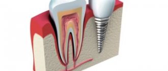
CAD/CAM systems are a technology for the development of prostheses, crowns and braces, based on the principle of preliminary creation of the required model and subsequent implementation into the final result. This term can be deciphered as “design and manufacture using computer technology” or in the exact decoding “Computer-Aided Design” and “Computer-Aided Manufacture”.
Nowadays, this method is used quite widely in a variety of fields, including dentistry, while previously it was used mainly in industrial areas.
CAD/CAM systems in dentistry
CAD/CAM systems began to be used in dentistry about ten years ago. They are used to make implants, dentures, dental crowns and much more. Products made using this technology are distinguished by high quality and reliability.
First, the future prosthesis is modeled using special software on a computer, and then the created model is reproduced on a milling unit.
Learn more about what CAD/CAM is
As the name suggests, this system can be divided into two:
- CAD is a way of organizing the automatic creation of a 3D model using special computer software;
- CAM is the direct production of the specified product using a pre-built three-dimensional template.
With the help of such systems, models of dentures are developed and then produced
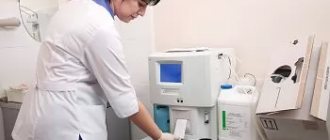
When using this system, the following specialized equipment is used.
| Equipment | Description |
| Scanner | It is used to create a virtual 3D model of the patient’s jaw and teeth. Such scanners can be divided into those that take a digital image directly in the oral cavity, and those that digitize a previously prepared plaster cast. |
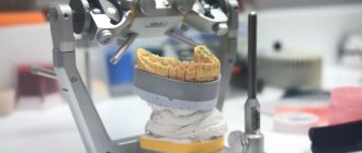
| Computer with pre-installed program | The jaw model taken by the scanner is processed using specialized software, where virtual prostheses for damaged teeth and subsequent restoration are simulated. This is somewhat reminiscent of an editor for creating three-dimensional images. The doctor working with such software independently sets the shape, relief and other necessary parameters for the future tooth model. The process usually occurs automatically. Once the design of the model is completed, a file with data about it is sent to the milling machine. |
| Milling machine | It automatically turns the finished product according to a model developed by a computer program. It contains the material from which the crown or veneer will be made - usually ceramic, zirconium oxide or metal. Moreover, zirconium oxide is most preferable for work of this kind, since it is better accepted by the body (its biocompatibility is even higher than that of gold) and does not cause allergic reactions. There are studies that confirm this. |
When making prosthetics using such systems, special equipment is used
Moreover, the list of products that can be made using this modeling system is not limited to frames for zirconium oxide crowns.
There are standards for the size of the edge of implants established by the English company Renishaw:
- 0-19 µm – the best level of marginal fit;
- 20-39 microns – good level;
- 49-79 microns – satisfactory fit;
- 80-119 microns – borderline acceptable level;
- more than 120 microns is the maximum permissible level for the structure to fulfill its functions.
Milling machine
PlanMill 50S.
First of all, let's look at what the combination of the two abbreviations stands for CAM. This is a powerful 5-axis PlanMill 50S milling machine. The machine was specially designed for dental laboratories, which means it can cut anything. If you work in a clinic, you might want to consider other models like the PlanMill 40S. If you are familiar with the ICORE Coritec 250i Wet, then you will definitely like the 50S as they have many similarities.
The milling cutter is equipped with a high-speed spindle and an automatic changer for 12 cutters. It can be used to mill discs, blocks and finished abutments made of titanium or cobalt chrome. PlanMill 50S is capable of both wet and dry milling of indications, and will handle everything from night guards to dental models.
Materials for the router.
Materials:
Drives:
- Cyrkon
- Wax
- PMMA
Blocks:
- Ceramics
- Composite ceramics
- Resin based materials
- Zirconium materials
Distinctive properties of each type of CAD technology
CAD is a system for modeling objects using a computer and specialized software. Now, in order to create a drawing, it does not take much time, you do not need paper and drawing sets, the ability to create models on a computer saves a lot of time.
Three-dimensional models are developed using CAD systems
Important! Any template is created in three-dimensional format and can be viewed from different angles. In case of errors and inaccuracies, any model and part can be quickly replaced, and as soon as all the necessary modeling steps have been completed, the project can be submitted for creation on the machine.
CAM is the direct process of executing a model according to a given template created using CAD technology. Computer systems aimed at regulating production mechanisms are also widely involved here. In this case, the machine operator is required to make appropriate adjustments so that the final object takes the desired shape and the execution process complies with certain instructions.
The result is a well-coordinated working system - using CAD technology, the implant model itself is compiled, and using CAM, the specialist manages the process of creating the part.
The prosthesis itself is manufactured using CAM technology
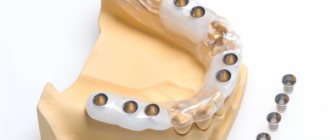
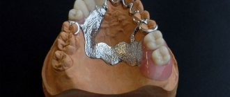
Functionality of CAD/CAM systems in dental clinics and laboratories:
- the ability to create models of veneers, bridges, crowns, inlays, etc.;
- setting up dental modeling automation – there is a built-in library;
- It is possible to model up to 16 teeth at a time.
- all manufactured templates can be saved in the system for future use;
- the manufacturing process takes five stages from the immediate start of work on the model to the operation of the milling machine.
Possibilities of innovative technology
Using the CAD/KAM system, you can design and form various objects used for orthopedic treatment:
- crowns;
- veneers;
- overlays;
- tabs;
- bridges.
CAD/CAM programs make it possible to create digital anatomical libraries to fully automate the modeling process. The resulting models are stored in the system for an unlimited period for further use. In one session, the program can form up to 16 dentures (crowns, veneers, etc.).
Compared to traditional prostheses made manually in dentistry, CAD/CAM structures do not injure the soft tissues of the oral cavity, do not cause discomfort and do not deform over time.
How can these systems be used in dentistry?
The most popular process where they are used is to make dental filling blanks and obtain the final product in the form of the filling itself. Due to the use of a certain amount of materials in dentistry to make implants, it is not always possible to achieve the desired result, which is highly reliable.
However, thanks to CAD/CAM systems, it is possible to expand the choice of materials used for the manufacture of fillings. For example, this way you can create durable, high-quality ceramic fillings.
Using such technologies, it is possible to produce fillings, crowns and dentures from various materials.
These are the advantages of using automated systems in prosthetics compared to conventional methods.
- It is possible to produce a base for a filling of a natural color that does not differ from the natural color of the enamel.
- Fillings made from ceramics are more durable.
- Materials such as ceramics are perfectly accepted by the body.
- It is possible to strengthen damaged teeth.
Capabilities and types of cad/cam systems
Manufacturing a dental bridge on a
CAD CAM machine, systems allow us to produce:
- crowns and bridge structures of various lengths;
- telescopic crowns;
- abutments for dental implants;
- veneers and inlays;
- provisional crowns.
There are 2 types of CAD CAM systems:
- closed systems that work with specific consumables, usually produced by one company;
- open systems that work with various consumables from different manufacturing companies.
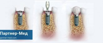
Process of installing crowns using an automated system
The method of manufacturing implants using this system can be considered the most modern and high-tech. Therefore, it is already widely used in high-level dental clinics.
Interesting! Crowns made using this method are distinguished by increased strength, ease of installation and use, and precise anatomical shape.
Step-by-step process for performing actions using CAD/CAM technology:
- preliminary preparation of dental tissues, installation of a temporary implant;
- making a digital impression, creating a model of the prosthesis and making it on a machine;
- installation of the finished prosthesis on a previously ground tooth with subsequent fastening.
This method of manufacturing implants is considered the most modern.
This procedure minimizes the possibility of medical errors or subsequent complications, but requires a high level of competence on the part of the dentist. Automated CAD/CAM systems have characteristics such as increased accuracy and short production times, even for technologically complex structures. Thus, this technique has a higher priority than the others.
Video - Making a prosthesis from zirconium oxide
Examples of computer-aided design programs
The profession of a modern developer requires serious training. They teach CAD in specialized universities. However, basic education is not a guarantee of success. The sector is actively developing. New products regularly appear on the market, requiring study and operating skills. It is becoming the norm for engineers to take advanced training courses. Software developers meet the needs of the users of their products. Paid programs include an important option - the ability to receive support and learn how to work.
It takes time to learn all the graphics capabilities of the software. Many developers offer a bonus for students. Thus, market leader Autodesk gives a license for students for three years when using 3ds Max. The functionality of the design program is almost the same as the expensive professional version. The cost of the basic Autodesk 3ds Max package for the current period is more than 60,000 rubles for one user. The amount is large even for an active engineer. Typically, such products are purchased by the enterprise.
Not only large enterprises have a need for 3D modeling. Today, three-dimensional design is in demand among individual entrepreneurs and just amateurs. To implement their ideas, they do not need to purchase products with a set of functions required in high-tech industries. You can find design programs for more reasonable prices, or use free versions with limited capabilities.
Designers working in CAD systems are well aware of the AutoCAD package. For many years now, he has enjoyed well-deserved respect for his ability to implement ideas with fairly simple, intuitive tools. The ability to work in both two-dimensional and three-dimensional space is supported. Projects are saved in standard CAD form. The cost of the product allows it to be purchased by medium and small companies. As a trial, the manufacturer gives you the opportunity to use the program for free for 30 days. During this time, a specialist with basic education will learn to use the basic functions and decide whether it is worth buying or not.
Professional products also include Pro/ENGINEER from the American developer Parametric Technology Corp. The original program engine is characterized by high performance and quality. It is possible to display the project in a photorealistic image in good resolution. The French brand CATIA is known to innovation specialists. The product is fully integrated with CAD/CAM/CAE systems and can be used in various areas of industrial activity, from mechanical engineering to construction.
The domestically developed 3D design program “Compass” is actively promoted on the market. The classic version of options for creating CAD projects. The interface, description, help are in Russian, which is the reason for its growing popularity. The function of creating text and graphic documents according to the ESKD standard is supported. The program is easy to learn and use.
It is impossible not to mention SolidWorks software. The program is adapted for wide use on medium-power computers. Not the richest functionality, but the available capabilities are quite enough to implement fairly complex projects. Large enterprises also use the program. The manufacturer offers a line of products for various purposes to solve all problems in CAD, CAM, CAE systems. The core of the graphic design is Parasolid's own development, which has both pros and cons.
Detailed manufacturing process
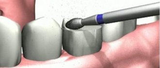
Let us consider in more detail the scheme for the development and implementation of a zirconium dioxide frame.
- Receipt of the impression of the patient’s jaw and teeth into the milling center.
- Scanning the template and converting it into a file that will be processed by a computer program. Next, using specialized modeling software, a template for the frame, superstructure, etc. is created. In this case, the CAD module (program) offers to select the required design, and the operator modifies it so that it becomes the desired shape.
- Having carefully examined the design model from all angles, you can specify various coating options, check all sections, and finally develop a frame that meets all the stated requirements.
- After the modeling process is completed, the file is sent directly to the milling machine, and the finished frame is already created on it. At the end of the work, a finished three-dimensional model is made from the required material. If the prosthesis is made of zirconium dioxide, it is sent further to a special oven for agglomeration (baking).
- In the oven, the workpiece reaches the required strength, acquires the desired size and color. This process occurs at a temperature of 520 degrees Celsius, then the finished prosthesis goes directly to the technician for work.
Prostheses are made according to a specific pattern
Prostheses made using CAD/CAM technology from a material such as zirconium dioxide have much higher performance than crowns made from metal-containing material.
Interesting! The dentures are as close as possible to the natural color of the enamel, which is set at the stage of making the frame.
The surface is covered with German Creation ceramics, which has increased light transmittance and a wider color spectrum.
Ceramics Creation
The thickness of such a frame does not exceed 0.4 mm, so grinding of tooth enamel can be minimized. However, this thickness does not in any way reduce the strength of the implant, since zirconium oxide is many times stronger than other materials. In addition, it is not subject to corrosion and deformation and lasts much longer.
Pros and cons of this technology
CAD/CAM in dental practice and dental prosthetics are very popular in modern clinics, as they have the following advantages:
- anatomical accuracy;
- the possibility of manufacturing from high-strength materials (for example, titanium or the aforementioned zirconium dioxide);
- can be used in working with the most advanced cases;
- the possibility of medical error is minimized;
- therefore, the human factor is practically excluded;
- high wearing comfort, the crown fits perfectly;
- zero level of injury.
Such technologies have many advantages
The doctor can demonstrate the digital model to the patient, and he will be immediately informed about the manufacturing and implantation process and what the result will look like.
Prostheses made using this method practically do not deform and do not change location. High manufacturing accuracy - about 25 microns (compare with hand casting - its accuracy is usually 100 microns or more).
Interesting! If zirconium oxide is chosen as the material, then the enamel and dentin will not be damaged.
Unfortunately, the main disadvantage of using this technology is its high cost. However, this is an excellent investment in your own health, given the increased reliability and lack of harm to the body.
The main disadvantage of making prostheses in this way is the high cost.
CAD-CAM Technology in Modern Dentistry
Don't you want to use CAD-CAM technology in your daily practice? High quality and minimal time costs are two indicators of a doctor’s successful work, especially when it comes to indirect restorations in dentistry. CAD-CAM technology allows you to reduce the number of laboratory stages of restoration, which often take a lot of time.
Doctors who work with CAD-CAM claim that CAD-CAM technology is very simple. The main thing is to master it and apply it in everyday practice.
Partial restorations using the indirect method
CAD-CAM technology is a unique combination of restoration quality, cost and time. Indirect partial restorations in dentistry are the most modern solution to many defects. They create strong cusps, adapt the restoration to the gum and provide excellent esthetics.
Photo 1
For a comfortable experience, a reliable treatment protocol must be used.
Initial situation: a patient after endodontic treatment and with a temporary composite filling on the mesial surface of tooth 16. The previous restoration did not restore the contact point and prevented the passage of dental floss.
Photo 2
The medial part of the old composite filling is removed and a rubber dam is installed. Immediately after removing the old composite filling, we begin restoration with dentin shade A2 (Filtek Supreme XTE).
Photo 3
After removing the rubber dam, the occlusal surface is prepared by 2 mm. A place is emerging for indirect restoration in dentistry. The depth of preparation may vary depending on the type and properties of the restorative material.
Photo 4
Demineralized enamel is prepared in the area of the distal marginal ridge. The marginal ridges were moved to the area where the wedges were located. This area is easily accessible for probes, brushes, and dental floss. Partial posterior restorations are considered to require extensive preparation. Modern preparation techniques are a combination of old techniques. Basic principles:
1. Invisible transition between filling and tooth
2. Access to all surfaces
3. Minimum volume of preparation
4. Flat surfaces
5. Unique geometric shape.
Photo 5
After removing the wedges and rubber dam, bleeding of the gums is possible. To stop bleeding, use 3M ESPE hemostatic astringent paste. After a 5-minute exposure of the paste, it is washed off with water and air.
Photo 6
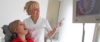
The work area is lightly powdered with a CAD-CAM contrast agent. An intraoral scan is performed (TrueDef).
Photo 7
Taking impressions to make CAD-CAM restorations requires different skills and movements compared to conventional silicone impressions. Therefore, special tools have been developed to help the doctor.
The Styleitaliano team, together with the Smile Line under the leadership of Dr. Gaetano Paolone, has developed a series of soft tissue retractors called “Photo-CAD”, specifically designed for simultaneous isolation of the tongue and cheeks when working on lower jaw teeth (Photo-CAD LOW), and for isolating the cheek on all the way to the second or third molars on the upper jaw (Photo-CAD UP). The name Photo-CAD comes from 1) the ability to act as a retractor for photography and 2) for making CAD (Computer Assisted Design) impressions.
Photo 8
The STL file is immediately sent to the laboratory (Giuseppe Mignani, Bologna). At the same time, the doctor solves other problems. With the classical approach to treatment, the dentist must design the restoration and carry out further work himself, spending a lot of time.
Photo 9
Checking occlusal relationships.
Photo 10
It is necessary to clearly establish communication between the laboratory and the clinic. Once the lab receives the file, the 3D design is produced fairly quickly: the file is sent back in about 20 minutes.
Photo 11
Modern materials such as lithium disilicate are often used for restorations with excellent results. However, laboratory-fabricated composite restorations still remain an alternative to ceramic restorations. Obvious advantages are the softness of the material and the absence of harm to antagonists, as well as simple correction if necessary and good workability. For this clinical case, LAVA ultimate was chosen, which has excellent properties.
Photo 12
The final shaping and polishing is done quite quickly, ensuring perfect anatomy.
Photo 13
The Overlay tab is adjusted and adjusted if necessary. If the fitting does not raise any questions, we proceed to isolating the working field and fixing the tab.
Photo 14
Contact points must be checked and adjusted with an abrasive rubber head until an ideal restoration-tooth transition, stability and conformity to the gingival margin is achieved.
Photo 15
CAD-CAM restorations are quite accurate and require only minor adjustments. It seems that the color of the restoration is far from ideal. However, after cementation, the tooth-restoration interface will likely disappear.
Photo 16
The quadrant is isolated and everything is ready to cement the restoration.
Photo 17
The restoration is immediately sandblasted with a pressure of 2 bar at a distance of at least 5 centimeters from the surface.
Photo 18
After careful sandblasting of the composite restoration with isolated adjacent teeth protected by matrices, selective acid etching of the enamel is carried out with 37% phosphoric acid for 15 seconds.
Photo 19
The cavity is treated with a universal adhesive system (Scotchbond Universal, 3M ESPE), brushed for 20 seconds and left for 40 seconds, after which excess material is removed with air. They do not polymerize.
Photo 20
The same adhesive is placed inside the restoration, and excess material is removed as described above.
Photo 21
Dual-curing cement is placed inside the restoration.
Photo 22
Excess cement flowing over the edge during polymerization.
Photo 23
Using a small instrument (Fissura, LM Arte, LM instruments, Parainen, Finland), excess cement is removed from all surfaces, including proximal ones.
Photo 24
A round condenser (Condensate, LM Arte, LM instruments, Parainen, Finland) holds the restoration in place, rarely leaking excess material. Approximal surfaces are treated with floss.
Photo 25
Excess material is removed with a brush.
Photo 26
Long-term polymerization.
Photo 27
The polymerized excess material is removed with a sharp instrument (Eccesso, LM Arte, LM instruments, Parainen, Finland), paying special attention to the proximal area.
Photo 28
Final view of the restoration.
Photo 29
Minimal adjustments to the occlusal surface.
Photo 30
Final view of the restoration.
The translation was made by Petrushchenko A. specifically for the OHI-S.COM website. Please, when copying material, do not forget to provide a link to the current page.
https://www.styleitaliano.org/
Brief overview of different models
CAD/CAM systems used in our country:
- Cerec;
- Katana;
- Organic, etc.
Overview of Dyamach systems
For the manufacture of prosthetic structures, open type DT2 milling equipment is used, which makes it possible to use almost any materials, including metals, polymers, ceramics, etc. It has increased accuracy, and the machine can operate continuously.
Advantages of models from this manufacturer:
- wide angle of rotation of the working axes (A by 360 degrees, B by +/- 43 degrees);
- spindle movement at high speed (up to 60,000 rpm);
- the ability to process complex metal structures and abutments (in particular, titanium);
- a wider range of cutters used (from 3 to 6 mm), while many similar models are limited to only 6 mm cutters;
- have a lower cost compared to other professional equipment;
- Less time is spent on milling.
Dyamach equipment
Interesting! The Dyamach DT-2 machine is equipped with a Mitsubishi engine, it allows you to increase the accuracy and speed of work. This system has an ideal price-quality ratio.
Overview of Roland systems (made in Japan)
These open systems feature reduced noise levels and extremely high precision in the production of zirconium products.
The advantages of the DWX 51D milling unit include the following factors:
- it is possible to process zirconium crowns with high precision; metal-free material Trinia, which has an increased level of strength, can be used;
- you can perform work simultaneously on five axes;
- accuracy is increased due to the fact that the tilt angle along the B axis is larger up to 30 degrees;
- It takes about 30 minutes to make one crown; if two are made at the same time, then the time does not exceed 45 minutes, therefore, when processing several workpieces at once, the time for one becomes less. 20 crowns will take approximately 6 hours;
- due to the special shape of the disc holder, the possibility of rotation is excluded;
- a cutter auto-change mechanism has been implemented;
- The device is equipped with an ionizer.
Roland Equipment
Here's what we can say about the DWX 4W glass-ceramic milling machine:
- you can work on three workpieces without stopping, which significantly increases the speed of work;
- it is possible to work with glass-ceramic workpieces;
- diamond cutters;
- milling can be performed along four axes with a rotation angle of 360 degrees;
- the ability to automatically feed tools at four stations is organized;
- spindle speed 60,000 rpm (Jaeger);
- water cooling, equipment cleaning system;
- indication system for notification of ongoing operations;
- good compatibility with many scanner models and various software;
- excellent sales conditions and guarantees compared to other manufacturers, high demand due to wide capabilities and good price.
Review of German-made Sirona milling machines
This is a flexible system, the functional parts of which work well both together and separately. These devices are available even for small laboratories, as they are in the middle price segment.
Sirona equipment
Pros of Sirona systems:
- high productivity increases the clinic’s profit;
- flexibility in working with functional software;
- the ability to upgrade devices and install additional modules.
Interesting! Devices produced by this company inLab MC XL and Cerec MC XL have high accuracy and speed; switching between different operating modes takes only a few minutes. When working with a large number of processed parts, this creates tangible benefits.
It is also worth paying attention to the inEos Blue scanner. It is equipped with an intuitive control system, easy to install add-ons and performs large-scale scanning.
inEos Blue Scanner
Italian equipment from ZirkonZahn
This is a closed system, it contains the following components: the milling unit itself, a scanner, a set of CAD/CAM software and a computer.
Advantages:
- the possibility of producing solid zirconium implants;
- no need to pay large sums for updates;
- materials from the company of high quality;
- there is the possibility of learning online;
- prompt and accessible support.
Interesting! This five-axis system has a more affordable price compared to its competitors, but its quality remains at a decent level, so it is perfect for installation in a dental clinic.
Equipment ZirkonZahn
Review of systems from the manufacturer Wieland (Germany)
This manufacturer is known for the fact that its equipment has the most compact dimensions. The Zenotech Mini system weighs only 45 kg and can be installed on a desktop. At the same time, the functionality does not suffer at all.
This is an excellent option for clinics and laboratories with a small area. The machine is equipped with four-axis technology, which allows you to perform any type of work.
Zenotech Select is a milling device with five axes, it has more functionality and power, but its price is higher.
Interesting! This manufacturer also supplies good scanners, for example, Zeno Scan S1000. They are great time savers and provide high manufacturing precision.
Wieland equipment
The advantages of CAD/CAM systems include the following:
- small size;
- easy-to-use software that does not require constant updating;
- high productivity, it is possible to produce 1800 units per month.
German equipment manufacturer IMES-ICORE
This manufacturer markets the CoriTec 550i model, which has the highest quality milling work when processing the hardest materials.
Axles with a granite base based on innovative developments allow you to achieve a perfectly smooth surface. The spindle speed reaches 80,000 rpm, which guarantees the highest precision; The resulting products are durable.
This model is from a higher price segment, but it justifies itself with advanced features and high standards of quality and reliability.
Pros of this model:
- performance is higher than that of competitors;
- ability to work around the clock;
- reliable electric motors with high precision;
- it is possible to work with various materials, including chromium and cobalt;
- highest precision of work.
Equipment IMES-ICORE
CAD systems
CAD system
(computer-aided design - computer-aided design support) is a computer-aided design system designed to perform design work using computer technology, and also allows you to create design and technological documentation for individual products, buildings and structures.
Generally, the acronym CAD
is considered the standardized English-language equivalent of the term
CAD
.
However, the concept of CAD is not a full equivalent of CAD as an organizational and technical system: for example, in GOST 15971-90 this phrase is given as a standardized English equivalent of the term “computer-aided design”. The term CAD in English can also be translated as CAD system, automated design system, CAE system. A number of foreign sources establish a certain subordination of the concepts of CAD, CAE, CAM. The term CAE is defined as the most general concept that includes any use of computer technology in engineering activities, including CAD and CAM. The term CAx (computer-aided technologies) is used to denote the entire range of various computer-assisted automation technologies, including CAD tools. The main goal of creating CAD
is to increase the efficiency of engineers by automating work at the stages of design and pre-production.
Thus, thanks to CAD, it is possible to achieve: - reduction in the complexity of design and planning; — reduction of design time; — reduction of design and manufacturing costs, reduction of operating costs; — improving the quality and technical and economic level of design results; — reducing costs for full-scale modeling and testing. As input information, CAD uses the technical knowledge of specialists who enter design requirements, clarify the results, check the resulting design, change it, etc. The computer-aided design system is implemented in the form of a set of application programs that provide design, drawing, and three-dimensional modeling of structures, flat or three-dimensional parts. As a rule, modern CAD systems include modules for modeling a three-dimensional three-dimensional structure (parts) and designing drawings and text design documentation (specifications, statements, etc.). Classification of CAD according to GOST 23501.108-85:
- type/variety of the design object - complexity of the design object - level of design automation - complexity of design automation - nature of documents issued - number of documents issued - number of levels in the structure of technical support
Classification of CAD (or CAD subsystems) by target purpose:
- CAD (eng. computer-aided design/drafting) - computer-aided design tools, in the context of this classification the term means CAD tools intended for automation of two-dimensional and/or three-dimensional geometric design, creation of design and/or technological documentation, and general CAD appointments.
— CADD (computer-aided design and drafting) — design and creation of drawings. — CAGD (computer-aided geometric design) — geometric modeling. — CAE (computer-aided engineering) — tools for automating engineering calculations, analysis and simulation of physical processes, carry out dynamic modeling, testing and optimization of products. — CAA (computer-aided analysis) is a subclass of CAE tools used for computer analysis. — CAM (eng. computer-aided manufacturing) — means of technological preparation for the production of products, provide automation of programming and control of equipment with CNC or GAPS (Flexible Automated Manufacturing Systems)). The Russian analogue of the term is ASTPP - an automated system for technological preparation of production. — CAPP (English: computer-aided process planning) — automation tools for planning technological processes used at the interface of CAD and CAM systems. Many computer-aided design systems combine solving problems related to various aspects of CAD/CAM, CAD/CAE, CAD/CAE/CAM design. Such systems are called complex or integrated. Generally accepted international classification of CAD/CAM/CAE systems:
- Drawing-oriented systems, which appeared first in the 70s.
(and are still successfully used in some cases). — Systems that allow you to create a three-dimensional electronic model of an object, which makes it possible to solve problems of its modeling right up to the moment of manufacturing. — Systems that support the concept of a complete electronic description of an object (EPD Electronic Product Definition). EPD is a technology that provides development and support of an electronic information model throughout the entire life cycle of a product, including marketing, conceptual and detailed design, technological preparation, production, operation, repair and disposal. The abbreviation CAD
in modern technical, educational literature and government standards stands for
“Computer-Aided Design System
,” although the decoding “System for Automation of Design Work” more closely corresponds to the abbreviation CAD, but it is more difficult to understand and is used much less frequently.
You can often hear a misinterpretation - “Automatic design system”
, which is wrong in its essence, since the concept “automatic” implies independent operation of the system, without human intervention, and in CAD some functions are performed by humans, and only certain design operations and procedures are automatic .
“Software for design automation”
is also not entirely correct , since it is too “narrow”: of course, CAD is now often understood only as application software for carrying out design activities.
However, in domestic literature and state standards, CAD is defined as a more capacious concept that includes not only software. Currently, the largest developers of CAD/CAM systems
are the following companies: - Parametric Technology Corporation (PMTC) - Pro/Engineer software, Windchill; — Dassault Systemes (DASTY) — CATIA, SolidWorks, ENOVIA CATIA, DELMIA software; — Autodesk (ADSK); — Unigraphics Solutions (UGS) — Unigraphics software, Solid Edge, iMAN, Parasolid; - Structural Dynamics Research Corporation (SDRC) - I-DEAS software.
print
VKontakte
System Features
It is worth saying a few words about the features of scanning implants among different systems.
- CEREC IN LAB company (SIRONA): use of three recognized notches with a recognition threshold of 100 µm
- PRECIDENT company (DCS): three notches, recognition threshold is the same as the previous one, 100 µm.
- HINT ELS system (HINT ELS GmbH): one recognizable notch, recognition threshold 150 µm.
- System EVEREST company (KAVO): a number of notches are not recognized, the recognition threshold is more than 150 microns.
Accordingly, the PRECIDENT and CEREC IN LAB systems have the best recognition threshold, which means they can accurately display microcracks and edges that may be invisible to other scanners. In this case, the virtual model will be identical to the real one.
Each system has its own characteristics
Differences
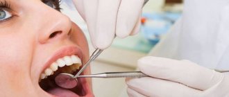
Let's look at the difference for the patient between crowns made using CAD/CAM systems and the conventional method.
Both crowns can be almost identical in appearance, and as a result, the patient will be provided with a restoration with a high level of aesthetics, it is possible to achieve a beautiful smile and full functionality of the teeth. However, when using automated modeling systems, a high speed of the prosthetics process can be achieved.
Note! Making crowns this way takes much less time.
Instead of a regular impression, you can use a scanner that works directly in the oral cavity, which is much more pleasant for the patient.
Making dentures this way takes little time.
The patient has the opportunity to observe the process of modeling his unique crown and watch how it is carved. It's informative, beautiful and interesting.
Preparation for prosthetics in both cases will be identical - this is a common procedure, including disinfection and restoration of teeth.
Let's sum it up
Computer technologies confidently take their place in modern dentistry. It can be predicted that in just a few years most modern clinics will use prosthetic technologies using CAD/CAM systems. In most laboratories trying to keep up with the times, such equipment is already widely used.
This system can easily be called the technology of the future, so it is worth paying special attention to studying the capabilities and features of various models to make it easier to make a choice.
Stages of prosthetics
Dental CAD/CAM technology does not require taking an impression of the patient’s teeth and casting a model, which simplifies the process of manufacturing orthopedic elements and reduces the time of prosthetics from the standard 2 weeks to 2 hours. You can install high-quality, accurate, comfortable crowns in one visit to an orthopedic dentist.
Prosthetics using CAD/CAM technology in dentistry is carried out in three stages:
- computer diagnostics;
- design of three-dimensional models;
- production and installation of objects.
First, the doctor performs standard orthopedic treatment to prepare the site for the future prosthesis. Then, using a virtual camera, he takes optical impressions, which he transfers to a computer program and models the anatomical shape of the prosthesis.
Here, in the program, the dentist tries on the orthopedic structure on a virtual projection of the patient’s jaw, after which he transmits the data to the control unit of the milling machine. Processing of the material for the future prosthesis is carried out mechanically or laser. The finished structure is fixed on the patient’s prepared teeth.