Where are they used?
Such connections are generally used to transmit only very small loads. Sometimes pins are used to secure parts together. There are also special shear elements of this type used as fuses. In addition to assemblies with shafts, such products are very often used to connect covers and housings.
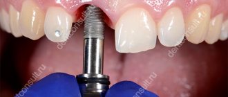
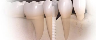
Another purpose of pin connections is prosthetics in dentistry. Using such elements, artificial teeth are attached.
Types of pins
When assembling various types of components, two main types of similar products are used:
- cylindrical;
- conical
Cylindrical pins, in turn, can be:
- spring split;
- perforated (with grooves).
Additional design elements of the pins may include threaded holes or protrusions. They are used for removing products from blind holes.
According to the functions performed in the assembly, three groups of pins are distinguished:
- installation;
- guides;
- fastening.
Pins
A pin is a fastener in the form of a cylindrical or conical rod, designed for stationary connection of parts, as well as for transmitting relatively small loads.
According to their shape, the simplest and most popular pins can be divided into cylindrical and conical DIN 1.
Cylindrical pin Conical pin
The taper of the pins is 1:50. Cylindrical pins can be unhardened DIN 7 or hardened DIN 6325; the hardness of the latter is 60±2 HRC.
The ends of the pin can be as follows:
flat beveled with sphere
Please note that according to GOST the length of the pin includes the ends, but according to DIN it does not.
Pins are high-precision parts: the tolerance range is usually assigned to m6, sometimes h8 or h11.
Pins of more complex shapes - pins with external and internal threads: DIN 258, DIN 7977, DIN 7978 and DIN 7979.
Another group of pins involves the presence of a longitudinal cut or a cut along the axis. They can be complete or partial. The most common are two positions:
Cylindrical spring pin with slot, light or heavy version (in TsKI - only heavy) DIN 1481;
The pin is notched cylindrical with three notches along the entire length and a chamfer DIN 1471.
Other pin options are shown in the figure below.
Pin connection: GOST
In most cases, when assembling assemblies, standard pins are used, manufactured in compliance with GOST standards. They are different for each specific type of product. Thus, the production of simple-shaped pins is regulated by GOST 3128-70 (cylindrical) and GOST 3129-70 (conical). Such parts are usually made from steel grade 45. But GOST allows the use of material grades A12, 10 kp, 20 kp, etc. for this purpose. Expanded products are made from spring steel. Sometimes pins of different types are made from non-ferrous metals.
Of course, the nominal dimensions of these elements are also regulated by standards. GOST also provides for permissible deviations of the latter. This allows you to assign typical pin fits to the holes of bushings, shafts, covers and housings.
The designation of these products includes:
- the word "pin";
- product type;
- its dimensions;
- designation of the standard.
The type is indicated only if it is clearly defined by the standard. In the “dimensions” field, the diameter of the product and its length are indicated. Sometimes tolerance fields are also entered here.
What is
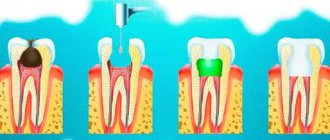
Connections of this type are of the detachable type. When creating them, the parts of the assembly are first drilled. Moreover, it must be joint. That is, the parts are first stacked with each other in the same way as they will be located in the unit later during its operation. After this, the actual drilling takes place.
At the next stage, the pins themselves are inserted into the resulting holes. Cylindrical elements of this type are installed very tightly. That is, the pin always has a slightly larger diameter than the hole prepared for it.
In the event that the unit will be subjected to repeated assembly/disassembly during operation, conical pins rather than cylindrical pins are provided for it. This allows you to extend the service life of the structure. Since the cylindrical pins are inserted into the holes of the parts very tightly, after disassembly and assembly the assembly may lose its original performance qualities. That is, the connection may simply not be too strong.
The pins work during operation:
- for cutting (along the joint surface);
- to crumple.
It is based on these characteristics that calculations are made to determine their suitability for use in a particular unit. The working surfaces of both the pins and the parts being connected can be subject to collapse.
Pin connections
Pins are used to fix the relative position of connected parts, as well as to transmit forces and moments.
Cylindrical pins
Pins are made for various fits. To prevent the pins with drilled ends from falling out (see Table 6.1.2), after inserting them into the through hole, they are riveted. For the same purpose, notched pins are used (see Table 6.1.3), which are kept from falling out by plastic deformation of the metal extruded when notching the grooves.
The dimensions of cylindrical pins with internal threads intended for installation in blind holes are given in table. 6.1.4. The flat on the side surface is used to allow air to escape from the blind hole, and the threaded hole is used to remove the pin.
Conical pins
The parameters of the pins installed in through holes, which ensure the dismantling of such pins when disassembling the connection, are given in Table. 6.2.1. To make it easier to dismantle conical pins from blind holes, pins with a threaded pin (see Table 6.2.2) or with internal threads (see Table 6.2.3) are used. Both designs provide protection for the threads from damage due to driving (a chamfer on the threaded hole or a cylindrical shank on the journal).
Examples of pin connections
Figure 6.3.1 shows examples of the use of pins when connecting parts with flat contact surfaces. A typical pin installation option is shown in Figure 6.3.1, a. If the pin is installed in a blind hole, then use a threaded pin for dismantling and a flat for the release of compressed air when installing the pin (Figure 6.3.1, b). An option for installing a pin, when the tool approach in the direction perpendicular to the joint plane is difficult, is shown in Figure 6.3.1, f. In such cases, pins located in the parting plane are also used (usually four pins, one on each side). More accurate fixation of parts is ensured by placing the pins in pairs in opposite corners (Figure 6.3.1, d). When transmitting minor circumferential and axial forces, the connections shown in Figure 6.3.2 (a-d) are used. They are more technologically advanced compared to keyed and splined ones and eliminate backlash, which is especially important during reverse movement. Therefore, such connections are widely used in instrument devices. Figure 6.3.3 shows examples of the use of special pins. The hollow split pin (Figure 6.3.3, a) provides satisfactory centering of parts and relative ease of installation without the use of special tools due to its high compliance in the radial direction. The advantage of a connection using an adjustable pin (Figure 6.3.3, b) is the simplicity of its design and installation, however, it is possible to reduce the tension of the pin during operation. The latter is excluded in the connection, where a tight fit of the pin is ensured by tightening the nut (Figure 6.3.3, c). When significant loads are applied in the plane of the joint, connections are used in which the shear load is transmitted both by the sleeve (pin) and by the friction forces at the joint caused by the tightening of the threaded connection (Figure 6.3.3, d - f).
Tell friends:
← Rivet connections
Next: Spline and profile connections →
Advantages and disadvantages
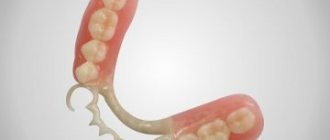
In the manufacture of various types of assemblies, in addition to pin connections, wedge, key, and spline connections can be used. All of them are of the detachable type. Threaded connections of this type using screws, studs and bolts, profiles, and terminals are also very often used. Each of these types has both its advantages and disadvantages.
The advantages of pin connections include primarily:
- simplicity of design;
- ease of assembly/disassembly;
- precise centering of the parts to be connected.
Such connections have basically only one drawback. In any case, a hole drilled for the pin will weaken the part in the future. Terminal connections, for example, do not have such a disadvantage.
At the same time, the sockets for the pins must be processed very carefully. Otherwise, the product may subsequently bend. The need for precise processing of the hole increases the cost of manufacturing the assembly part.
Features of using cylindrical pins
The assembly of pin connections when fastening machine parts is usually performed using smooth products. In the same way, the usual fixation of structural elements of the machine during its operation is usually carried out. In this case, two smooth pins are most often used.
To fix the position of parts, perforated products of this type can also be used. Their main advantage, compared to smooth ones, is that they do not require reaming the holes. In the absence of additional fastenings, such elements are also more reliable in terms of falling out. As with the use of conical pins, when using drilled cylindrical pins, assembly/disassembly of the connection can be carried out repeatedly during operation.
In static connections, cylindrical products are installed with interference. In moving ones, they are mounted with the obligatory riveting of the ends. Spring cylindrical pins are usually mounted in lightly loaded connections. The tension when using them is created by reducing the diameter of the hole. Installation types of pins in fit connections are installed with an interference fit with one of the parts. On the other hand, they are mounted with a H7/h6 or H7/js6 fit.
Conical products
Pins of this variety are made with a taper of 1:50. This ensures their subsequent self-denial in the nodes. Such products are used to transmit torque and to connect covers with housings almost as often as cylindrical ones.
Simple conical pins are usually installed in through holes. In this case, during installation they are simply driven in from the opposite side of the connection. If the hole is not through, a tapered pin with a thread is installed into it for pulling out.
Adjustable products of this type are used in connections that may be subject to shocks and shock loads during operation of the mechanism. In addition, they are installed in those units in which parts move at very high speeds. The ends of such pins are usually separated after installation.
Cylindrical pin-key
The diametrical cross-section of the pin is checked for shearing, and the lateral surface for crushing (Fig. 3).
Rice. 3. Diagram of forces acting on a cylindrical pin-key
Crumple area:
circumferential force:
pin crushing strength:
cutting area:
pin shear strength:
moment transmitted by the connection:
The permissible stresses, depending on the strength of the shaft and hub materials and the operating mode, are selected in the range [σcm] = 60...150 MPa (smaller values are chosen for cast iron hubs and under uneven and shock loads, and larger values for steel hubs).
Features of installation in the node
The parts are drilled for connection with a pin, as already mentioned, in the assembly. In some cases, these elements are additionally fixed to avoid falling out. This is done, for example, when installing dismountable connections. In this case, additional fixation is provided with a ring of 0.5-0.8 mm wire.
In non-separable connections, the pins are usually cored. But in some cases, products with drilled ends can also be used. After assembly, such pins are flared.
When using conical products, in some cases the self-rejection condition may not be met. This happens quite often, for example, in units subject to vibration or operating under conditions in which the temperature changes sharply. In such connections, conical pins must be secured additionally.
Set overview
Unimetric models are titanium anchor conical pins with square heads.
According to the installation method, they are classified as passive elements, which means:
- the model is needed to enhance the strength of the reconstructed element or to prevent cracking of the walls of the pulpless unit.
- The product is not threaded.
- It is fixed in the oral cavity with special cement or filling material.
Unlike analog devices from other manufacturers, Unimetric pins have the following characteristics:
- No thread . Due to free fixation, pressure and internal tension are not created.
- They are produced in two varieties : L – elongated head, S – its shortened modification. Each type is created in two diameter options: 1 and 0.8 mm.
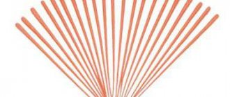
- There is a convenient color marking for each size type.
- High strength with lightness of the entire structure , which is ensured by the manufacturing material.
- If necessary, adjustments in length are allowed.
- There are special circular retention grooves that improve the fixation of the pin in the canal and prevent their loss.
- The presence of sliding lips in the upper section , which improves the fixation of the filling material.
- Biocompatible with oral tissues , chemically passive, non-corrosive.
- The products are universal in use.
- Allows you to perform restoration in one step.
The kit includes drills - penetrating and calibrating. The first is marked with a single colored ring and has two slightly protruding rings corresponding to a long and short pin head. The second drill is indicated by two colored rings.
A set of intra-channel clamps with a large diameter contains in addition a universal (or intermediate) drill, which creates a gradual transition from the penetrating type of drill to the calibration type.
Selection and calculation of pin connections
The dimensions of the products used to transmit torque depend primarily on the diameter of the shaft (within d pcs.<0.3d). The shear strength of the pin is selected using the following formula:
- t av=4T/dxd2pcs.<.
Here T is the torque and is the permissible shear stress. The last parameter is looked at in special tables. The connection is checked for collapse with a thin hub using the formula:
- Q av=2T/d(Dd)d pcs.<.
Here /d(Dd)d pcs. — conditional crushing area, — permissible bearing stress for steel.
Calculation of a conical pin for strength
The diameter of the mounting pin is taken structurally. The diameter of the fastening pin is determined based on the pin per shear.
Rice. 2. Force diagram for calculating a conical pin
The average pin diameter dsh is determined from the condition of shear strength along two shear planes (Fig. 2):
cutting area –
circumferential force –
where T is the torque.
Pin diameter:
When a force F is applied to the pin, perpendicular to its axis, the shear strength condition is:
The permissible shear stress for a pin made of steel of the specified grades is [τav] = 35...75 MPa; lower values – under load with shocks and shocks.
Repair
In addition to crushing or shearing, in connections of this type, defects such as wear of the hole and the appearance of cracks in the parts themselves can also occur. It is not allowed to further operate the units if any of the four problems occur. Repair of the unit must be carried out. In any case, a unit with a defect will not work for very long.
The actual repair of pin connections is, of course, carried out in compliance with certain standards. In most cases, defective pins are discarded and replaced with new ones. However, GOST still allows, for example, to expand worn holes for another larger pin. It is also allowed to weld old holes and drill new ones in their place.