F (Fig. 1) is generated between the teeth of the mating gears In addition, the sliding of the teeth between them generates a friction force Fƒ=ƒF , where ƒ is the friction coefficient. The force Fƒ is small compared to the force F , therefore, when deriving the calculation formulas, it is not taken into account, i.e., it is assumed that the interaction force between the teeth is directed normal to their profiles. Under the influence of forces F and Fƒ, the teeth are in a complex stressed state. Their performance is influenced by bending stresses σF in the cross sections of the teeth and contact stresses σH in the surface layers of the teeth. Both of these stresses, variable over time, can cause fatigue failure of the teeth or their working surfaces. Bending stresses σF cause tooth breakage, and contact stresses σH cause fatigue chipping of the surface layers of teeth.
Breakage of teeth is a dangerous type of destruction, since in this case not only the gear train, but also the shafts and bearings can fail due to broken pieces of teeth getting into them. Tooth breakage occurs as a result of heavy loads, especially impact, and repeated repeated loads that cause fatigue in the tooth material. To avoid tooth breakage, they are designed to bend. Fatigue spalling of tooth surfaces is a common and dangerous failure mode in most enclosed, well-lubricated gears. Chipping consists of the fact that, under high contact stresses, fatigue cracks appear on the working surface of the teeth (usually on the legs, near the pole line). This leads to chipping of small particles of tooth material and the formation of small pock-shaped depressions, which then, under the influence of oil pressure, pressed with great force by the mating tooth into the resulting depressions and cracks, grow and turn into shells. To prevent teeth from chipping, they are designed for contact strength. Rice.
1 The main types of destruction of the working surfaces of the teeth, in addition to chipping, also include abrasive wear of the teeth and their seizing. Abrasive wear of the working surfaces of the teeth occurs in open gears when dust, dirt, and grains of sand come into contact with the teeth, acting as an abrasive material. The teeth of closed gears of such machines as mining, agricultural, construction, transport and others operating in an environment contaminated with abrasive particles are also subject to abrasive wear. In open and closed gears, the teeth of which are subject to wear, chipping occurs very rarely. The working surfaces of the teeth of these gears wear out before fatigue cracks appear in them. Teeth seizure occurs in highly loaded and high-speed gears due to rupture of the oil film or lack of lubrication of the teeth. In this case, particles of material are torn off from the working surface of the teeth of one of the gears and welded to the working surface of the teeth of another gear, forming build-ups that lift up the mating teeth, leaving deep grooves on them.
To avoid breakage and chipping of the working surfaces of the teeth, they are designed for bending according to bending stresses σF ; for contact strength based on contact stresses σH .
The teeth of closed gears are calculated for contact strength and bending. The main calculation of the teeth of these gears is their calculation for contact strength. As for the teeth of open gears, they are usually limited to calculating them for bending.
Let's consider the calculation of the teeth of the most common gears: cylindrical spur and helical and bevel spur gears.
Calculation of the strength of teeth of cylindrical involute closed gears of external gearing, consisting of steel gears with a modulus of 1 mm and higher, is standardized by GOST 21354-75. The standard establishes the structure of formulas for calculating teeth for contact fatigue of the working surfaces of teeth and for fatigue of teeth during bending. To simplify the calculation of teeth, small deviations are adopted in certain GOST formulas that have little effect on the final result of the calculation. According to GOST 21354-75, the coefficients common for calculating contact strength and bending are designated K , specific coefficients for calculating contact strength are Z , and for calculating bending are Y. When calculating teeth for contact strength, the index H (Herz is the author of the theory of calculating contact stresses), when calculating teeth for bending, which is performed along the tooth stem, the index F .
Rice. 2
Calculation of teeth for contact strength.
Calculation of teeth for contact strength is performed for engagement at the pole, since chipping of teeth begins at the pole line. The Hertz formula for the highest contact stresses during compression of cylinders in contact along generatrices is taken as the initial one (Fig. 2),
where
E is the reduced modulus of elasticity of gear materials; μ —Poisson's ratio; ρpr is the reduced radius of curvature of the profiles of the meshing teeth in the engagement pole; q=F/lk - normal load per unit lk of the tooth contact line; F is the pressure force between mating teeth. When calculating, instead of q substitute wHt - the specific calculated circumferential force and take into account that the circumferential force is deviated from the line of action of the normal pressure force by an angle αtw .
Then the reduced modulus of elasticity
where
E1 and E2 are the elastic moduli of the gear and wheel material, respectively. If the materials of the gear and wheel are the same, then E=E1=E2 . Reduced radius of curvature of a spur gear where ρ1 and ρ2 are, respectively, the radii of curvature of the gear and wheel tooth profiles;
plus sign for external, minus for internal gearing. Since (Fig. 2)
and that from the equalities
For helical gear
where
βb is the main inclination angle of the tooth line.
After substituting the value ρpr into the formula, we obtain from the formula
or where
ZH is the shape coefficient of the mating surfaces of the teeth in the meshing pole: ZM is the coefficient that takes into account the mechanical properties of the materials of the mating teeth:
Zε is introduced into the formula .
Thus, the initial calculation formula for the verification calculation of cylindrical gear teeth for contact strength, as given in GOST 21354-75, is written in the form
where
[σH] is the permissible contact stress for the teeth.
For spur gear at αtw=α=20° ZH=1.76 . When calculating a helical gear, you can take βb=β . For teeth of steel gears at E=2.1×10⁵ MPa and μ=0.3 ZМ=275×103 Pa½ . If one or both gears are not made of steel, then the values of E and μ for the materials of these gears must be substituted into the formula.
Coefficient Zε for spur gears
for helical gears
Approximate end overlap coefficient
For an approximate calculation of a spur gear, one can take εa=1.6 , which corresponds to Zε=0.9 .
Specific design circumferential force
where
Ft is the design circumferential transmission force; KHα is the coefficient of uneven load distribution between teeth in helical gears; KHβ is the coefficient of uneven distribution of load along the length of the contact lines as a result of errors in gearing and deformation of the teeth; KHv is the coefficient of dynamic load occurring in the meshing (see table); bw is the working width of the gear ring. Rice.
3 For spur gears KHα=1 . For helical gears, its value is taken according to (Fig. 3, a) depending on the peripheral speed v of the gear and the degree of accuracy (curves with numbers). The coefficient KHβ can be approximately determined by (Fig. 4) depending on the type of gear, the hardness of the tooth surface and the coefficient ψbd=bw/dw1 , where dw1 is the initial diameter of the gear; the numbers on the curves correspond to the gears indicated on the diagram. To convert surface hardness in HRC and HV HB units, a corresponding graph is given in (Fig. 5).
Rice. 4 Fig.
5 Permissible contact stress
where
[σH] is the limit of contact fatigue of tooth surfaces, corresponding to the basic number of stress cycles (see table); sH —safety factor; ZR is a coefficient that takes into account the roughness of the mating surfaces of the teeth; Zv is a coefficient taking into account the peripheral transmission speed; KHL - durability coefficient. Safety factor of gears with a homogeneous material structure SH=1.1 ; with surface hardening of teeth SH=1.2 . Coefficient ZR=0.9…1 ; a higher value refers to the greater roughness of the working surfaces of the teeth. Coefficient Zv=1…1.16 ; the lower the transmission speed and the harder the teeth, the lower Zv . At v≤5 m/s Zv=1 . For an approximate calculation, you can take ZRZv=1 . KHL coefficient is determined by (Fig. 6) depending on the ratio NHE/NH0 , where NHE is the equivalent number of stress cycles in the teeth, corresponding to the working number of transmission cycles with a constant loading mode, and NH0 is the basic number of stress cycles in the teeth, which is taken according to graph (Fig. 7) depending on the hardness of the working surface of the teeth. Rice. 6 Fig.
7 Equivalent number of voltage cycles when operating the transmission with a constant load
where
c is the number of identical gears meshing with the gear being calculated; n is the rotation frequency of the calculated gear, min-1; t is the duration of operation of the transmission under load over the design service life, h; when the transmission operates with variable loads (Fig. 8, a) where Tmax is the maximum torque transmitted by the gear during time t over the entire service life of the transmission at wheel speed n ; T1, T2, ..., Ti - torques transmitted by the gear wheel during time tl, t2, ..., ti , respectively, at rotation speed n1 , n2 , ..., ni . If, with an unstable tooth load, NHE/NHO>1, then, as follows from the graph (Fig. 6), KHL=1 . Rice.
8 Let's transform the formula into a form convenient for practical use. To do this, let us substitute into it instead of the specific calculated circumferential force wHt its value, taking into account the formulas and with the replacement bw=ψbaaw where ψba=bw/aw is the coefficient of the width of the gear rim along the center distance. Then, taking into account that dw1=2a/(u+1) and dw2=2au/(u+1) , we obtain the following formula for testing the calculation of teeth for contact strength:
where
T2 is in N×m; аw — in mm; σH , [σH] - in MPa.
When designing the teeth of a cylindrical gear for contact strength, the interaxal transmission distance aw , since according to GOST 2185-66 (ST SEV 229-75) it is the main standard parameter of external spur gears for gearboxes made as independent units. ψba and the gear ratio u are also standardized . Therefore, for the indicated gears, the values of aw and ψba must be consistent with GOST.
From the formula it follows that
Where
For spur gears Ka=495 , and for helical gears Ka=430 .
For gears built into machines, it is convenient to carry out the design calculation of the gear for contact strength so that the initial diameter dw1 of the gear can be determined using the calculation formula. Substituting into the formula
the value of
wHt taking into account formulas, etc. with the replacement bw=ψbddwl , where ψbd=bw/dw1 is the coefficient of the width of the gear rim along the initial diameter, we obtain where T1 is the torque transmitted by the gear;
coefficient For spur gears Kd=770 , for helical gears Kd=675 .
When calculating cylindrical gears of internal gearing in the formulas
instead of u+1 you need to substitute u-1 .
The permissible contact stress [σH] for the teeth of spur gears is determined separately for the gear and wheel and the smaller of them is taken as the calculated one. When calculating the teeth of helical gears, in which the gear teeth significantly exceed the hardness of the wheel teeth, the calculated contact stress
where
[σH1] and [σH2] are the permissible contact stresses of the gear and wheel teeth, calculated by the formula; [σH]min – minimum permissible stress.
In formulas aw and dw - in mm; wHt - in N/mm; T1 and T2 - in N×m; σH and [σH] - in MPa. KHβ coefficient is taken according to the graph (Fig. 4). The rim width coefficient ψba for gearboxes is taken equal to: for gear wheels of improved steels with an asymmetrical arrangement ψba=0.315…0.4 ; for gears made of hardened steel ψba=0.25…0.315 ; with a symmetrical arrangement of gears relative to the supports ψba=0.4…0.5 ; for mobile gear wheels of speed boxes ψba=0.1…0.2 Standard values of the coefficient ψba are given in the article gear reducers. The rim width coefficient ψbd is taken: with a symmetrical arrangement of gears relative to the supports ψbd=0.4…1.6 ; with an asymmetrical arrangement, but rigid shafts ψbd=0.3...1.4 ; with a cantilever arrangement of gears ψbd=0.2…0.6 .
The coefficients ψbd and ψba are related by the dependence bw=ψbddw1=ψbaaw whence ψbd=ψbaaw/dw1=ψba(dw1+dw2)/(2dw1) , or
When short-term overloads are applied to the teeth, it is necessary to check the working surfaces of the teeth for contact strength based on the maximum contact voltage:
where
σH max is the maximum design stress when the teeth are overloaded with the maximum torque Tmax ; [σH]max — permissible maximum contact stress for teeth, Pa; σH is the calculated contact stress caused by the design torque T1 and determined by the formula or For gear teeth and heat treatment by normalization, improvement or volumetric hardening with tempering [σH]max=2.8σT , where σT is the yield strength of the tooth material in tension; for teeth with heat treatment - carburization, contour hardening after heating with high-frequency frequency - [σH]max=HRC40 ; for nitrided teeth [σH]max=HR3 . The calculation of teeth using the formula is carried out separately for the wheel and for the gear.
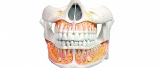
Types of gear damage
⇐ PreviousPage 7 of 11Next ⇒a) Broken teeth.
There are two types of tooth fracture. Fracture from large overloads, and sometimes from misalignment of shafts and uneven load across the width of the gear rim, and fatigue fracture occurring from prolonged action of alternating bending stresses, which cause fatigue of the tooth material.
Figure 2.3.2 Types of tooth surface damage
Fatigue cracks most often form at the base of the tooth on the side where tensile stresses arise from bending. To prevent fatigue fracture, the following are used: wheels with positive displacement when cutting teeth; heat treatment; shot peening; rigid shafts, increase the module, etc.
b) Fatigue chipping of the working surfaces of the teeth. The main type of tooth surface destruction for most closed high-speed gears operating with lubrication. Occurs due to prolonged action of alternating contact stresses, causing fatigue of the tooth material. Chipping usually begins near the pole line on the tooth legs, where the greatest frictional force develops, promoting plastic flow of the material and the formation of microcracks on the surface of the teeth. The development of cracks is facilitated by the wedging effect of the lubricant, which is pressed into the cracks of the teeth during engagement. Repeatedly, this action leads to the chipping of metal particles on the surface of the teeth and the formation of small pits, which then turn into cavities. When chipping occurs, the conditions for the formation of a continuous oil film are disrupted, metal contact appears, followed by rapid wear or scuffing of the surface. To prevent fatigue chipping, the hardness of the tooth surface and the degree of their accuracy are increased, the type of oil is chosen correctly, etc. Since contact stresses are the cause of fatigue failure, the main criterion for the performance and development of closed gears is the contact strength of the working surfaces of the teeth. In this case, the calculation of teeth for bending is carried out as a test. In gears operating with significant wear (open gears), no chipping is observed, since wear of the surface layers of the teeth occurs before cracks appear.
c) Wear of teeth.
The main type of destruction of the teeth of open gears, as well as closed ones, but not sufficiently protected from contamination by abrasive particles (dust, grains of sand, wear products, etc.). Such gears are found in agricultural, transport, lifting machines, etc. As the initial involute tooth profile wears out, the meshing gaps increase, dynamic loads and increased noise occur. The strength of a worn tooth is reduced due to a decrease in cross-sectional area, which can lead to tooth fracture. The main measures to prevent wear are increasing the hardness of the teeth, protecting against contamination, etc.
d) Teeth jamming
Occurs predominantly in high-speed high-speed transmissions. At the point of tooth contact, high pressures and temperatures develop, the oil film breaks and metal contact appears. Here, a kind of welding of metal particles occurs, followed by their separation from a less durable surface. The resulting growths on the teeth lift the surfaces of other teeth, leaving wide and deep grooves on them in the sliding direction. To prevent jamming, the hardness of the working surfaces of the teeth is increased, anti-seize oils and other measures are used to prevent wear.
16. Calculation of the strength of a cylindrical friction gear
Check calculation of gears with metal rollers.
The main criterion for the performance of friction gears with these rollers is fatigue strength. Substituting the Hertz formula (5) into formula (4) to determine the highest contact stresses and performing some transformations, we obtain the formula for the verification calculation
(15)
where a -
center distance, mm;
Epr—
reduced modulus of elasticity, MPa;
f
is the friction coefficient (see Table 1);
Т1—
torque on the drive shaft, Nmm;
Kc —
clutch reserve coefficient;
and ≥
1 - gear ratio;
b—
working width of the roller rim, mm;
—
permissible contact stress for a less durable material, MPa (Table 2).
Table 1. Sliding friction coefficient values for various materials
| Contact pair material | f |
| Steel on steel or cast iron (with lubricant) | 0,04-0,05 |
| Cast iron (dry) according to: | |
| steel or cast iron | 0,1-0,18 |
| textolite | 0,15-0,25 |
| fiber | 0,15-0,30 |
| skin | 0,20-0,50 |
| pressed paper | 0,40-0,50 |
| rubber | 0,35-0,70 |
| ferrodo | 0,30-0,35 |
Table 2. Allowable contact stresses, modulus of elasticity for rollers made of various materials
| Material | E | |
| MPa | ||
| Hardened steel (with good lubrication) | 600-800 | 2,1 · 105 |
| Gray cast iron grades from SCh 10 to SChZO | 420—720 | 1,1 · 105 |
| Textolite | 80-100 | 6 · 103 |
Design calculation.
Substituting expression (9) into formula (15) and performing some transformations, we obtain a design calculation formula for determining the center distance of the friction transmission from the condition of contact strength:
(16)
where is the coefficient of the roller rim width based on the interaxle distance, .
Check calculation of gears with non-metallic rollers
(textolite, fiber, rubber, etc.). For these gears, the main performance criterion is wear resistance. The material does not obey Hooke's law.
Normal load per unit length of contact lines
(17)
where T1
— torque on the drive roller, Nmm;
Kc
is the clutch reserve coefficient (see Table 1);
u
≥ 1 — gear ratio;
b
— rim width of the smaller roller, mm;
f
is the friction coefficient (see Table 1);
a —
interaxal distance, mm;
[q]
- permissible load per unit length of the contact line for a less durable material, N/mm.
Values [q]
for some materials of contacting pairs (one material is steel or cast iron) the following:
[q],
N/mm
Fiber………..34-39
Rubber………..10—30
Skin………14.5-24.5
Tree……….2.4-4.9
Design calculation.
Substituting into formula (17) and solving the equation for a,
we obtain a design calculation formula for determining the center distance of the friction transmission from the condition of wear resistance:
(18)
Sequence of design calculations.
1. Depending on the operating conditions, the material of the rollers is selected and, according to Table 2, is taken , E
or for less durable material.
2. According to Table 1, the friction coefficient f
, after which the coefficient is taken = 0.2 ÷ 0.4;
Ks
.
3. Using formula (16) or (18), the interaxle distance is calculated.
4. Determine the geometric dimensions of the rollers: D1
- diameter of the driving roller [formula (7)],
D2
- driven roller (8);
b
is the width of the rim of the rollers (9).
Using formula (6), the actual interaxle distance a is specified.
5. Using formula (14), the pressing force is determined.
6. The transmission is checked by peripheral speed v < vmax=
(7 ÷ 10) m/s.
7. Test calculation of transmission strength is carried out using formulas: (15) or (17). It should be borne in mind that the permissible underload of the transmission is no more than 10 %,
overload - no more than 5%.
The belt drive (Fig. 14.1) consists of driving 1 and driven 2 pulleys and a belt 3 put on them. The transmission may also include tensioning devices and guards. It is possible to use several belts and several driven pulleys. The main purpose is to transfer mechanical energy from the engine to transmission and actuator mechanisms, as a rule, with a decrease in rotation speed.
⇐ Previous7Next ⇒
Site search:
Calculation of teeth for bending.
The calculation of teeth for bending, as well as the calculation for contact strength, is carried out taking into account a number of factors that influence the fatigue resistance of teeth during bending and are expressed by various coefficients: the theoretical CT of stress concentration in the design section of the tooth; coefficient Yf of the tooth shape; coefficient Yε , taking into account the overlap of teeth; coefficient Yβ of tooth inclination; coefficient KFα of load distribution between teeth (see Fig. 3, b); coefficient KFβ of uneven load distribution across the width of the gear rim; coefficient KFv of the dynamic load occurring in the gear during operation of the gear.
When calculating teeth for bending, the tooth is considered as a beam, rigidly clamped at one end and loaded with a force F applied to the top of the tooth (Fig. 8, b). This load position is the most dangerous, since the leverage of the force relative to the dangerous section of the tooth is of greatest importance. The dangerous section of a tooth is taken to be the section at its base in the zone of greatest stress concentration.
Let us transfer the force F (Fig. 8, b) along the line of action to a point located on the axis of symmetry of the tooth and decompose it into two components: F cos α′ σF in the dangerous section of the tooth , and F sin α′ , which causes in tooth compressive stress σc . The angle at the top of the teeth is slightly larger than the profile angle α .
Although the maximum stress occurs on the compressed (non-working) side of the tooth, its strength is calculated based on the stress on the working side, since fatigue cracks and destruction of teeth begin, as experiments and experience in operating gears show, on the stretched side of the teeth.
Calculated bending stress of teeth in the dangerous section of the tooth on its working side (Fig. 8, b)
or where
b is the working width of the gear ring; s is the thickness of the tooth in the dangerous section; l is the arm of the tooth-bending force relative to the dangerous section; bs2/6 is the moment of resistance to bending of the dangerous section of the tooth.
Let us substitute into the equation instead of the force F its expression through the circumferential force Ft from the formula
and multiply the numerator and denominator of the right side of the equation and divide by modulus m, then or where is a dimensionless quantity that depends on the shape of the tooth and is called the tooth shape coefficient.
Let us substitute into the formula instead of the circumferential force Ft its expression through the specific calculated circumferential force
where
bw is the working width of the gear ring; bw=b . Then we obtain a calculation formula for testing the calculation of teeth for bending in the following form: where [σF] is the permissible bending stress for the teeth.
Substituting into the formula instead of the circumferential force Ft its expression through the torque Ft = 2 × 10³T1/dw1 , where Ft is in N, T1 is in N×m and dw1 is in mm, we obtain a formula for testing calculations for bending of teeth of cylindrical gears depending from torque T1 transmitted by the gear:
where
ψbd=bw/dw1 is the coefficient of the width of the gear rim along the initial diameter of the gear. When designing teeth for bending, the modulus of the teeth is calculated: or where . For straight gears Km=14 , for helical gears with εβ≤l Km=11.2 and with εβ≤l Km=12.5 . Axial overlap coefficient εβ=btg β/pt. In formulas (12.68), (12.69) and (12.70), wFt is in N/mm; T1 - in N×m; σF and [σF] - in MPa; m - in mm.
m obtained by the formula should be rounded to the nearest larger standard value.
When designing teeth for bending, the number of teeth z1 of the gear is specified, and the number of teeth of the wheel
For gears without offset, it is recommended to adopt z1≥17 teeth (no tooth cutting). To reduce the overall dimensions of low-speed gears, z1≥12 teeth are allowed. In special cases, z1 is accepted even less. In high-speed gears, in order to reduce noise, it is recommended to use z1≥25 teeth.
Rice.
9 The value of the tooth shape coefficient YF for gears of cylindrical gears of external gearing is taken according to the graph (Fig. 9) depending on the displacement coefficient x and the number of teeth z of a spur gear or on the equivalent number of teeth zv for a helical gear. Since YF corresponds to the shape of the teeth in the normal section (which for oblique teeth does not coincide with the plane of action of the circumferential force Ft ), according to which the teeth are calculated for bending, then for oblique teeth YF is determined not by the real number z , but by the equivalent zv , corresponding to the divisive diameter of the equivalent spur gear dv . The section normal to the teeth by plane NN of a helical gear (Fig. 10, a) forms an ellipse with semi-axes a=d/(2 cos β) and b=d/2 . The radius of curvature of the ellipse re when teeth mesh in the pole ρ=a2/b=d/(2 cos2β) simultaneously represents the radius of the pitch circle of an equivalent spur gear. Consequently, the pitch diameter of the equivalent cylindrical wheel is dv=2ρе=d/cos2β or mzv=mtz/cos2β=mnz/cos3β , from which, given that m=mn , it follows
For helical gears, the coefficient Yε=1 . For spur gears, in an approximate calculation, you can also take Yε=1 .
Rice.
10 For spur gears, coefficient Yβ=1 ; for helical teeth
At β≥42° Yβ=0.7 .
For spur gears the coefficient KFα=1 . For helical gears, its value is taken according to the graph (Fig. 3, b) (curves with numbers) depending on the peripheral speed v of the gear and the degree of accuracy. The value of the coefficient KFβ can be approximately determined from the graph (Fig. 4) depending on the type of gear, the hardness of the working surface of the teeth and the coefficient ψbd=bw/dw1 ; the numbers on the curves correspond to the gears indicated on the diagrams. The values of the dynamic load coefficient KFv are presented in table. The values of the coefficient ψbd=bw/dw1 are given in the “Additional materials” section.
Allowable bending stress for teeth
where
σF lim b is the endurance limit of teeth during bending, corresponding to the base number of stress cycles; sF —safety factor; KFL - durability factor; KFc is a coefficient that takes into account the influence of bilateral application of load on the teeth; with unilateral action KFc=1 .
Safety factor sF=1.7…2.2 (higher value for cast pieces).
Durability factor
where
NF0 and NFE are the base and equivalent number of voltage cycles, respectively. For gears with tooth surface hardness HB≤350 , as well as with a ground transition surface of the teeth, the root index is m=6 , for gears with HB>350 and an unpolished transition surface m=9 . The basic number of voltage cycles is NF0=4×10⁶ . Equivalent number of cycles of voltage change NFE when the transmission is operating with a constant load where c is the number of identical gears meshing with the gear being calculated; n is the rotation frequency of the calculated gear, min-1; t is the duration of operation of the transmission under load over the estimated service life. The equivalent number of cycles of voltage change NFE when the transmission operates with variable loads (Fig. 8, a) When NFE>NF0 take KFL=1 .
The value of the coefficient KFc is taken: with a one-sided load on the teeth, KFc=1 , and with a double-sided load, KFc=0.7...0.8 (larger value for HB>350 ).
If the material of the gear wheels is the same, then the calculation of teeth for bending should be done using a gear whose tooth thickness at the base is smaller and, accordingly, the tooth shape factor YF is greater than that of the wheel teeth. If the material of the gear teeth is stronger than the material of the wheel teeth, which is usually accepted, then the calculation of the teeth for bending should be carried out using the gear for which the ratio [σF]/YF has a lower value. It is recommended that the material of the gear and wheel teeth be taken such that the ratio [σF]/YF for both gears is approximately the same.
When exposed to short-term overloads, the teeth are checked for plastic deformation or brittle fracture when bending under maximum load:
where
σFmax is the maximum design bending stress in the teeth of the gear when they are overloaded with the maximum torque Tmax ; [σF]max - permissible maximum bending stress for teeth; σF is the design bending stress for the teeth caused by the design moment T1 and determined by the formula. The value [σF]max can be taken: with tooth surface hardness НВ≤350 [σF]max =0.8στ, where στ is the tensile yield strength of the tooth material; with hardness HB>350 [σF]max =0.6σв, where σв is the tensile strength of the tooth material. The teeth are calculated using the formula for a less durable gear wheel.
Calculation of straight teeth of bevel gears for contact strength.
Experimental data have established that the load capacity of a bevel gear is lower than a cylindrical gear. In accordance with this, a coefficient is introduced into the calculation formulas for bevel gear teeth that takes into account the reduction in load capacity compared to the teeth of cylindrical gears and is taken equal to 0.85. Formulas for calculating the strength of the teeth of bevel gears are similar to the formulas for the teeth of cylindrical gears.
The cross-sectional areas of the teeth of a bevel gear and the size of the specific load q per tooth are proportional to the distances from the apex of the initial cone, and therefore the strength of the teeth of bevel gears can be calculated for any cross-section. It is customary to calculate the teeth of bevel gears using the middle section located in the middle of the length of the teeth.
In the calculation formulas for the contact strength of the teeth of bevel gears, the reduced radius of curvature is taken into account, which for straight teeth of a bevel gear with an axial intersection angle of 90° is determined by the diameters of equivalent cylindrical spur gears (see Fig. 10, b):
Because
and it follows from the formulas that
Comparing the formulas, we notice that in the formula instead of u+1 it is written √u2+1 . This circumstance allows us to write down the calculation formulas for the contact strength of straight teeth of bevel gears in the following form: verification calculation
or design even where
ψbd=bw/dm1=0.3…0.6 .