222
In devices for expanding the upper dentition, screws and springs are used as power elements. The first is usually the Hyrex screw.
The latter have different designs depending on the tasks facing the orthodontist. Maxillary expanders typically use a pin, pear, or Coffin spring.
In mandibular appliances – the Koller design.
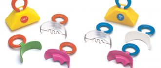
Serpentine spring or pusher
Designed for vestibular movement of teeth. The movement can be body-based or with rotation around an axis. This depends on the design features of the serpentine spring manufacturing. With an unequal number of bends (Fig. on the left), which are located in mutually opposite directions, translational and rotational movements occur, with the same number (Fig. on the right) - only translational, since the forces that act rotationally are balanced.
The force that the spring develops depends on its length, the diameter of the orthodontic wire, the number of bends and their width, as well as the elastic properties of the orthodontic wire. With an increase in the diameter of the wire and a decrease in the length of the acting arm or bending radius, the spring force increases. Most often, springs with two semicircular bends are used. Making springs with more than three bends is impractical, since the active part of the spring becomes long, elastic, easily slides off the moving teeth and interferes with the movements of the tongue.
Oval protraction spring
Or a double-arm pusher is designed to move a group of incisors. The active part is oval bends in the amount of 1 to 3, which are made from orthodontic wire with a diameter of 0.5-0.7 mm. If it is necessary to move the entire group of cutters, the spring is made of wire with a diameter of 0.6-0.7 mm.
A modification of the oval spring is our proposed 8-shaped double-arm protracting spring with a flat (for body movement) or round (for movement with rotation around an axis) head.
The springs are activated by increasing the distance between the bends.
Coffin spring connecting palatal plastic pelota. 1 page
Varieties of group A bite formers differ from each other in the presence of springs that correct the position of the upper incisors, canines and premolars, additional arches, and screws (Fig. 16.10, 16.11).
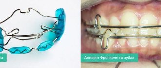
The Frenkel method is used to treat distal occlusion during the period of active jaw growth. Its essence lies in eliminating the pressure of the lips and cheeks on the alveolar
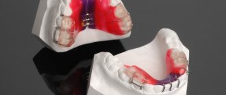
Rice. 16.11. Diagnostic models of the jaws of patient K.
a: on the left - before treatment, in the middle - Bimler bite former on models, on the right - after treatment; b — Bimler bite former on a model of the upper jaw.
processes and dentition in areas of their underdevelopment, in the normalization of lip closure, tongue position, their functions and relationships. R. Frankel proposed an orthodontic device - a function regulator. Its main parts - labial pelota and buccal shields - are located in the vestibule of the oral cavity. The volume of the oral cavity itself increases as a result of an increase in the bite, which helps to normalize the position and function of the tongue.
A function regulator [type (FR-I) is used to eliminate anomalies in the position of the anterior teeth and distal occlusion, combined with narrowing of the dentition and protrusion of the upper anterior teeth (Fig. 16.12).
Clinical and laboratory stages of manufacturing function regulators. The first stage is taking impressions from the jaws and preparing working models. When making plaster parts of the jaws, the transitional parts of the mucous membrane should be preserved throughout their entire length.
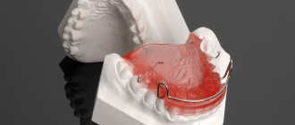
Fig. 16 12 Stages of manufacturing a type I Frenkel function regulator
Second stage Heated strips of wax 1.5-2 mm thick are applied to the bite roller of the wax template and glued with molten wax. The wax template is inserted into the mouth and the constructive bite is determined. The cutting edges of the incisors are set in marginal closure so that the upper incisors minimally overlap the lower ones, and the lateral ones the teeth were separated. If there is a sagittal gap equal to 8 mm or more, the lower jaw is moved forward by 5-6 mm. Models of the jaws, compiled using a wax template in a constructive bite, are plastered in an occluder or Grotto retainer. After the plaster has hardened, the bite template is removed.
The third stage is the manufacture and fitting of the function regulator. When taking impressions from the jaws, the transitional fold of the mucous membrane from the vestibular surface of the alveolar process is stretched by the edge of the tray, impression material and smoothed, and therefore its depth and volume are displayed inaccurately. The plaster model of the lower jaw is corrected in the anterior area in the area of the transitional fold of the mucous membrane by engraving it vertically and downward to a depth of 5 mm on both sides of the frenulum of the lip. Lateral shields should contribute to the development of the apical base of the dental arch in the transversal direction. The model of the upper jaw is engraved in the area of the first premolars. and fangs, sometimes in the area of the tubercles of the upper jaw at the level of the transitional fold of the mucous membrane . When turning the lower fangs around the axis the lingual surface of the canine crowns is engraved in order to increase the pressure of the lingual arch on them and help correct their position. If there are no three between the teeth, then engrave a model of the jaw in the area of contact points between the teeth GU III II | II III IV or 4 3 2 I 2 3 4. and also between 6_V | V 6 or 6 5 I 5 b (in the presence of second permanent molars - between 7 6 | 6 7) per wire (0.9-1 mm) This is necessary so that the lingual and palatal arches, wire loops on the canines and palatal the clasps, when bent from the vestibular side of the alveolar process to the palatine or hyoid, were located between the corresponding teeth, contributed to the best stabilization of the apparatus and the distal movement of the upper teeth (Fig. 16 13, 16 14).
After engraving the plaster models of the jaws, the boundaries of the function regulator are outlined with a pencil, its individual details are depicted. The anterior border of the lateral shield begins from the transitional fold of the mucous membrane on the upper jaw between the canines and the first premolars or first temporary molars and extends to the transitional fold on the lower jaw, lower the border passes in the deep part of the transitional fold of the mucous membrane; in the distal area it smoothly passes into the upper border, which also runs in the deep part of the transitional fold. It goes around the place of attachment of the buccal muscles, passes deep into the engraved area of the model and roundly passes
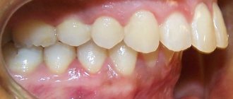
a b Fig. 1613 Diagnostic models of the jaws of patient P before (a) and after (6) orthodontic treatment with a Frenkel function regulator, indicating the dimensions of the lateral segments of the dental arches
Rice. 16.14. Contours of hard and soft tissues copied from lateral teleroentgenograms of the head of patient R before (a) and after (b) treatment.
The development of the jaws in the transversal direction with malocclusion is usually delayed, therefore the lateral shields of the function regulators FR-I and FR-II should not touch the alveolar process of the upper and lower jaws. To do this, wax pads are placed on the plaster models. Their thickness depends on the severity of the narrowing of the dental arches, but should not exceed 2.5 mm. A thicker layer of wax is applied in the area of the teeth to achieve greater expansion of the dentition. In the area of the transitional fold it should be thinner. Wax pads are not used under the lower lip pads, since distal displacement of the lower jaw creates a gap between the pads and the alveolar process. After applying the wax pads and removing the excess, the cooled with a wet cotton swab until shiny Thanks to this, the inner surface of the side panels regulator becomes smooth and does not need to be polished. The wax pads are cut with a razor at the level of the interocclusal space, which makes it possible to separate the plaster models of the jaws for ease of bending and strengthening the wire them .
To manufacture wire parts steel orthodontic wire with a diameter of 0.9-1 mm and a set of forceps (pliers, crampon pliers, round nose pliers and three- are used . It is necessary that the ends of all wire parts are located at an equal distance (0.7 mm) from the surface model and wax spacers. The parts of the wire parts that are free from plastic should away from the mucous membrane . They are placed, if possible in the natural recesses of the outer surface of the alveolar process to prevent injury to the mucous membrane of the lips and cheeks. The ends of the wire parts fixed in the plastic should be in the middle of it at a distance of 0.7 mm from the outer and inner surfaces of the shield or panel. The thickness of shields and caps should not exceed 2.5 mm. The thickness of the outer layers of plastic is 0.7-0.75 mm; in the shields has a diameter of 0.9-1 mm.
Details for the upper jaw. The vestibular arch transmits pressure from the mandible and lip through the appliance to the upper incisors, which contributes to their palatal inclination. To bend the vestibular arch, a wire 120-150 mm long is used, which depends on the width of the incisors and the size of the three between them. Rounded bends are made in the area of the fangs . They should touch the mucous membrane. The ends of the wire are bent back and slightly downwards parallel to the surface of the wax. At the level of the intercuspal fissure of the first permanent molar, they are bent towards the wax at a right angle. After fitting and correcting the arch, its ends are pressed into the wax.
Loops on the upper canines transfer pressure to the canines and premolars, which helps to delay the growth of the upper jaw and the distal shift of these teeth. The loop is made from a piece of wire 60-70 mm long, which is bent starting from the middle of the vestibular surface of the canine crown. The loop should not be adjacent to the crown in this area, so as not to interfere with the expansion of the dentition. Between the lateral incisor and the canine, the wire is bent towards the palate and goes around the neck of the canine, 1 mm away from the edge of the gum. The distal arm of the loop is placed in the space between the 3rd and 4th upper teeth so that it touches the mesial surface of the 4th tooth. Then it is bent distally without touching the buccal area. side of the premolar, and place the serpentine-curved end parallel to the surface of the wax. The end of the loop should enter the side shield at the level of the chewing surface of the teeth.
The palatal clasp connects the cheek pads, resists compression of the function regulator and its deformation in the transversal direction, and transmits pressure to the first permanent molars in the distal direction. The clasp is bent from wire 150-180 mm long, which depends on the depth of the palate and the width of the dentition in the molar area. A pencil mark is made in the middle of the wire, which should correspond to the midline of the sky, after which a U-shaped bend is made. It is placed in the area of the palatal vault without touching it (with a distance of 1 mm). The ends are roundedly bent somewhat anteriorly along the slope of the palate towards the interdental contacts between the 5th and 6th teeth, bent through the contact points, pressing them to the mesial surface of the first permanent molars, then bent upward in the form of U-shaped fixing brackets, free the ends of which (stoppers) are bent towards the chewing surface of the first permanent molars into the intercuspal groove. The stoppers should be spaced from the chewing surface of the teeth and not interfere with their dentoalveolar elongation. When the regulator is tilted, the stoppers rest on the chewing surface of the molars, which prevents injury to the gingival papilla and transitional fold
Details for the lower jaw For the bracket connecting the lower labial pelotes, use a piece of wire 30 mm long, which is bent in the middle to the shape of the frenulum of the lower lip. Its lateral sections are made zigzag, placed 7-8 mm below the necks of the lower incisors and removed from the surface of the jaw model by 0.75 mm. The bracket is fixed on the jaw model in the area of the lip frenulum with sticky wax. The paired parts connecting the labial pads with the cheek shields are made of wire 50-60 mm long. In the anterior section, the ends of these parts are placed parallel to the ends of the zigzag curved bracket connecting the labial pads, but 1 mm below them, and then bent upward and backward. Then the wire is bent in the distal direction, and near the edge of the wax pad it is bent in the vestibular direction. The last bend is made distally, almost at a right angle. The ends of the wire are placed parallel to the surface of the wax. These sections of the part must be equal, which is important for the correct correction of the device during the treatment process. At the level of the middle the necks of the first permanent molar bend at a right angle towards the wax. Excess wire is cut off, its ends 2-2.5 mm long are immersed through wax into a plaster model.
The lingual arch serves as a guide when moving the lower jaw into the position of constructive occlusion and when there is vestibular deviation of the lower incisors in cases where there are appropriate indications. To bend it, take a piece of wire 150-180 mm long, which depends on the width of the incisors and the depth of the oral cavity. For greater precision in operation, the lingual arch is first bent from soft wire with a diameter of 0.2 mm. The areas to be burned are marked on it. Then cut a steel wire of the same length and calcinate it in the middle part between the marks
The lingual arch should remain rigid in the areas corresponding to the middle of the ascending bends in the sublingual region. First, the middle part of the arch is bent, which is placed on the dental cusps of the lower anterior teeth. Starting from the distal surfaces of the canines, the arch is lowered. In the area of the floor of the mouth at the level of the roots of the first premolars, it is bent roundly , the ends are directed to the areas between the canines and premolars, cross the chewing surface between these teeth and bend backward parallel to the wax, without touching the vestibular surface of the lateral teeth. The length of the ends of the wire before they are inserted into the wax should be within 15 mm. The curves of the lingual arch should be placed opposite the roots of the first premolars. During a distal shift of the mandible, the lingual surface of its alveolar process should slide along these bends without causing injury. It is necessary to ensure that they only slightly move away from the mucous membrane and, when in contact with it, orient the position of the lower jaw. They should not be bent forward to avoid injury to the mucous membrane.
With malocclusion, incorrect positioning of the head and bending of the cervical spine are often observed (Fig. 16 15, 16.16). Treatment through a function regulator in combination with therapeutic exercises helps to eliminate both disorders in the neck area and general morphological and functional disorders
R Fiankel proposed several varieties of FR-I. The FR-Ia function regulator is used to treat neutral rhicus with deep incisal overjet, protrusion of the upper anterior teeth and retrusion of the dentoalveolar arch in the breech area of the lower jaw. In addition, this device
Fig. 1615 The shape of the cervical spine in case of postural disorders is used to treat distal occlusion in cases where the sagittal gap between the incisors is no more than 5 mm and the discrepancy in the closure of the lateral teeth does not exceed half the width of the premolar crown. The FR-Ia design has two technical innovations compared to the FR-I. The ends of the staple and connecting wires located in the lower labial pelots are bent in a zigzag manner, which prevents the rotation of the pelots. The loop of the palatal clasp is replaced with a flat U-shaped bend, which increases the rigidity of this part and increases the stability of the structure. The palatal clasp is bent from a wire with a diameter of 1 mm.
The FR-Ib function regulator is used in the treatment of distal occlusion with protrusion of the upper anterior teeth of moderate severity, i.e. in the presence of a sagittal gap of no more than 7 mm and a discrepancy in the ratio of the lateral teeth equal to half the width of the premolar crown. When determining a constructive occlusion, the lower jaw is advanced until the marginal closure of the incisors Instead of a lingual arch, a lingual plastic shield is made, which is placed in the sublingual area from 5 [ to [ 5 and attached with wire parts to the side shields placed between the 4th and 5th teeth. The lingual shield should not touch teeth B two protracting springs are strengthened there, which, if necessary, are activated for the vestibular deviation of the lower incisors. With the normal location and inclination of these incisors, the springs are significantly spaced from their lingual surface. In these cases, the lower jaw is set in the position of a constructive bite using a lingual shield
FR-Ic is used to treat distal occlusion with severe protrusion of the upper anterior teeth and significant discrepancy in the relationship of the lateral teeth. This adjuster is designed to
is 16 16. Teleroentgenograms of the head of patient N
t~110
- treatment at the age of 8 years, b - after treatment with a function regulator ^c 13 children)
The design corresponds to FR-Ib, but has two screws located in the side panels. The lower segment, in which the labial pads, lingual guide shield and the end of two screws are fixed, is cut out sectorally. When the screws are unscrewed, the segment moves forward, which allows the lower jaw to gradually advance, prevent excessive tension in the muscles of the maxillofacial area and help the patient more quickly master the function regulator. The upper segment moves posteriorly, which promotes distal movement of the upper teeth. |
Engle's apparatus of simple design is a non-removable mechanically operating apparatus that transmits pressure | impact on the teeth due to the springy properties of the vestibular arch:
ligatures, nuts and elastic rubber rods Currently<| instead of bandages for supporting teeth, rings C1
horizontal tubes soldered to them and additional rings for moving teeth with hooks, buttons, vertical levers, etc. They are used for fixation | sations ligatures. In combination with the Angle apparatus, removable or non-removable devices are used according to indications for the separation of 1 bite. Using this device, you can eliminate the incorrect position of individual teeth, expand or narrow dental arches, correct the relationship of the dentition in the sagittal and vertical directions,
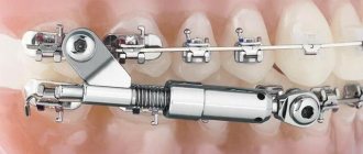
A sliding arch is used for oral inclination of i incisors using single-maxillary, intermaxillary or extraoral traction. ^ It should be adjacent to the vestibular surface of the crowns of the upper incisors and slide freely in the support tubes under the action of rubber traction. A standard Angle arch is used, from which the thrust nuts are removed, or an arch is bent from a piece of orthodontic wire with a diameter of 1-1.2 mm. ^ The hooks between the canines and the first premolars are soldered to the arch and they are bent anteriorly. Between these hooks and | With the ends of the tubes on the rings fixed on the supporting molars, rubber rings are pulled. As a result of their contractions, the pressure of the arc on the incisors increases and at the same time the location of the supporting teeth changes, which move mesially. To prevent such a complication, intermaxillary traction is used (Fig. 16.17), with the help of which it is possible, simultaneously with the oral inclination of the upper incisors, to achieve vestibular movement of the lower front teeth and mesial movement of the lower lateral teeth For this purpose, bend an arch for the lower dentition, solder hooks to it in the area of the lower 5 teeth and bend them back. Then the lower incisors and other teeth are fixed with metal ligatures, rubber rings are tightened
Fig. 1617 Extraoral (a) and intermaxillary (b) traction to correct distal occlusion
As a support, you can use a lingual arch soldered to the rings on the abutment teeth, and hook the rubber rings onto the hooks mounted on the vestibular surface of the rings. Flip hooks are made through the cutting edges of the incisors to prevent the arch from moving towards the gingival papillae and increasing vertical pressure on the incisors Hooks are made from strips of stainless steel sheet 0.5 mm thick, 4-5 mm wide and 8-10 mm long. The location of each flip hook is marked on the arc, after which they are soldered to the arc.
E N Angle improved the arch apparatus he proposed by introducing into its design locking devices (edges), welded or soldered to rings for supporting and moving teeth (Fig. 16.18).
The Gulyaeva apparatus is an intraoral non-removable arc apparatus with functional guiding and mechanical action. It consists of a sliding arch for the upper dentition with hooks soldered in the area of the canines and premolars, flip hooks for the incisors, soldered at one end to the arch, the other to an inclined plane that moves the lower jaw forward. This removable part of the apparatus is inserted into tubes soldered with on the vestibular side of the ridges on the supporting teeth Support rings are strengthened on the teeth with cement To tilt the upper incisors in the palatal direction, a single-jaw rubber rod is used. For this purpose, rubber rings are hooked onto the hooks on the arch and the distal ends of the tubes. Under the influence of the apparatus, retrusion of the upper incisors and mesial shift of the lateral teeth occur. B Therefore, after the removal of the first premolars, the Gulyaeva apparatus can be
Rice. 16 18 Engle's apparatus of complex design - edgewise technique | (scheme)
used for the purpose of orthodontic treatment for movement;
according to the indications of the lateral teeth to the place of the removed ones, but the rays”;
at the final stage of treatment, in
Begg's apparatus is a non-removable orthodontic optical apparatus consisting of rings, on the vestibular side of which special locking devices are welded to strengthen a thin, light round wire arch, position" \
heated in direct contact with the teeth (Fig. 16.19). This 'design successfully combines the advantages of simple arches"| j Engla, i.e. the possibility of free inclination of the teeth in all directions, with the achievements of the edgewise technique, which allows the teeth to be moved body-wise (Fig. 16-20).
In the first stage of treatment, a thin, lightweight Begg orthodontic arch with a diameter of 0.41 mm, fixed in locking devices, freely tilts the crowns of the teeth. To change the position of their roots, it is proposed to use an auxiliary thin arch with a diameter of 0.36 mm.
The first and second stages of manufacturing the Begg apparatus are the same as in the manufacture of edgewise equipment. However, instead of braces, other orthodontic locks are welded to the rings on the teeth being moved, namely with locking pins. Oval tubes with a length of 6.35 mm and an internal diameter of 0.91 mm are welded to the support rings for the first or second molars.
The third stage - the production of an active round dental arch with a diameter of 0.41 mm - begins with determining its length. Take a piece of wire 105-110 mm long. One end of it is inserted into the left support tube so that
Fig. 1619 Locking device of Bsgg-technique (diagram)
Fig. 1620 Begg technique - expansion of the dentition
Kiss. 16.21. Sequence of application of dental arch options in the Begg apparatus (1-10).
so that it protrudes beyond its limits by 1.5 mm. A mark is made at the level of the middle of the vestibular surface of the canine and a hook or loop is bent to strengthen the intermaxillary traction. The middle part of the arch is made smooth or contoured according to the shape of the dentition. After this, the second hook for intermaxillary traction is bent near the canine crown of the opposite side. The distal projections of these hooks should fit snugly against the locking devices on the canine teeth, and the hooks should
away from the teeth (Fig. 16.21). A simple round orthodontic arch is used in the first stage of treatment. It can be bent using Adams, Aderer or tongs with cone-shaped jaws (one round, the other flat).
When indicated on the arch, additional vertical bends are made to the dentition, create space for teeth, mesiodistal inclination of the teeth, eliminate diastema the dental arch To make such an arc, larger of wire is required Its difference from the arch described above is that after bending the stopper and one hook for intermaxillary traction, vertical bends are made in the form of loops 8-10 mm high. The loops are placed between adjacent teeth so that they do not touch their vestibular side. If it is necessary to expand the dentition , then loops are made; if there are indications for its reduction, semicircular bends are made. The sections of wire located in the locking device are bent at an angle to the crown of the tooth, which allows it to be rotated along its axis. The bending of the arch is completed by making a hook for intermaxillary traction and a stopper in front of the support tube on the opposite side. The stoppers should be directed towards the transitional fold of the mucous membrane so that they do not interfere with the closure of the teeth.
For mesiodistal movement of individual teeth, loops are used, which must be in contact with the locking devices, so that after compression or stretching of the vertical semicircular bends, pressure is transferred only to the teeth being moved. You can reduce the size of the dentition and eliminate gaps between teeth using a single-jaw or intermaxillary rubber and spring rod.
After achieving the desired inclination of the teeth, the second stage of treatment begins. An active round arch with a diameter of 0.41 mm is replaced with a passive support-holding arch with a diameter of 0.64 mm. It is shaped into a dental arch and secured in locking devices. Then the auxiliary arch is bent with vertical bends to rotate the roots of the upper and lower incisors. To make it, take a piece of wire with a diameter of 0.4-0.5 mm. Mark areas for each protrusion on the arc and bend them. The angle of their deviation from the vertical plane should be 75-80 °. The production of the arc is completed after bending two fixing hooks to strengthen the auxiliary arc on the main one.
The auxiliary arc is not welded to the main one, but rather screwed to it. The auxiliary arch should rest against the tertical support protrusion made in the middle of the support arch. It is strengthened together with a smooth arch. The vertical loop on the auxiliary arch can be adjusted so that it acts from the vestibular side on the crown of the tooth in the area of its neck or incisal edge. The lever action causes the tooth to rotate around the main arc. If the vertical loop acts on the cutting edge of the tooth, then its root moves vestibularly, if on the neck of the tooth, then it tilts in the lingual direction. To tilt the roots of teeth in the mesiodistal direction, Kisling, Broussard springs, single-jaw or intermaxillary rubber traction are used. The thicker 0.64 mm diameter main archwire is more effective than the 0.41 mm diameter archwire because it better keeps the abutment teeth from moving unwantedly due to reaction force. When using a Begg appliance with differentiated application of forces, it is important to remember that no tooth should be rigidly held by the locking device. All locking devices and ligatures should provide a small amount of play in the arch so that the teeth can tilt and move along the main arch under the influence of small forces.
The second type of distal bite (Class II according to Angle) is characterized by retrusion of the upper incisors and often the lower ones, deep blocking bite, excessive growth of the upper jaw and underdevelopment of the lower jaw. The principle of treatment for this type of malocclusion is the vestibular deviation of incorrectly positioned upper incisors, after which it is possible to push the lower jaw forward and stimulate its growth in length. When the dentition narrows, their expansion is indicated. Often, distal movement of the upper lateral teeth that have moved mesially, or the removal of individual teeth in the upper jaw, most often the first premolars, is required. Treatment is completed by correcting the position of the lower anterior teeth, which in most cases are inclined orally (Fig. 16.22, 16.23).
The choice of design of orthodontic appliances depends on the period of formation of the occlusion and the type of anomaly (the seventh, eighth and ninth types of distal occlusion according to Malygin). During the period of temporary occlusion, they strive to eliminate bad habits - suction of the upper lip, pressure with fingers on the upper teeth, normalize swallowing, perform plastic surgery of the shortened frenulum of the tongue, refer the patient to a speech therapist, and recommend therapeutic exercises. In case of traumatic occlusion, a plate for the upper jaw with a screw, a sectoral cut for the vestibular deviation of the upper incisors, clasps and a bite platform for the lower incisors are used.